You can create virtual welds for assemblies in aP Pro (instead of a CAD application). aP Pro supports multiple weld processes, weld types, and weld prep / cleanup processes.
You can:
Welding Parts
You can also create welds for edges and holes of a single Sheet Metal or Bar & Tube part. Part-welding processes are included in the Part Assembly secondary process group, and this capability is licensed along with the Welding module.
To weld a part, right-click on a GCD and select Edit Operation, then in the Operation Sequence Selection dialog, define weld processes and types.
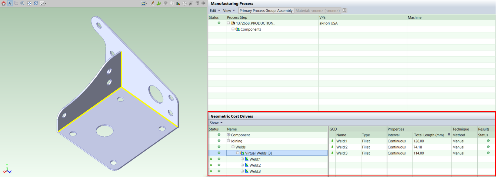
View Virtual Welds
-
Open an assembly.
-
In the Geometric Cost Drivers pane, click Joining > Welds > Virtual Welds. The list of virtual welds opens.
-
Click on a virtual weld to display its properties in the GCD pane and to highlight it in the Component Viewer.
Create Virtual Welds
Open an assembly, then for each weld you want to create:
-
Click the Welding tool (
 ) in the Component Viewer tool bar.
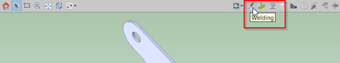
The mouse cursor within the Component Viewer turns into a welding torch, the same as on the Welding button. The weld tool pane opens.
-
In the Component Viewer, move the cursor over the assembly and select an interface (edge) between two parts where you want to create the weld. This interface line should turn yellow.
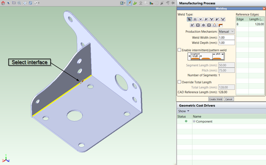
You can create a virtual weld consisting of multiple interfaces, by clicking each one required. However, this is still treated as a single weld item, which can affect time and cost calculations.
-
In the Weld tool pane, enter your weld properties:
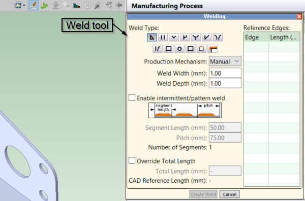
Where:-
Weld Type: Select the type of the weld - for example, fillet or V-groove. Different weld types are represented with schematic pictures. Move the mouse cursor over a picture to see the name of the weld type.
-
Production Mechanism: Select manual or robotic production mechanism.
-
Weld Width (mm): Enter the width of the weld in millimeters.
-
Weld Depth (mm): Enter the depth of the weld in millimeters.
- Enable Intermittent/Pattern Weld: Check this box to create a non-contiguous weld - if you do not want continuous welding along an interface. For an intermittent weld, define:
- Segment Length (mm): The length of a weld segment in the intermittent weld.
- Pitch (mm): The distance from the beginning of one weld segment to the beginning of the next weld segment.
- Override Total Length: By default, aPriori automatically calculates the length of a weld, and displays this value in the CAD Reference Length field.
You can override this value by clicking the checkbox and entering your own value in the Total Length field.
-
-
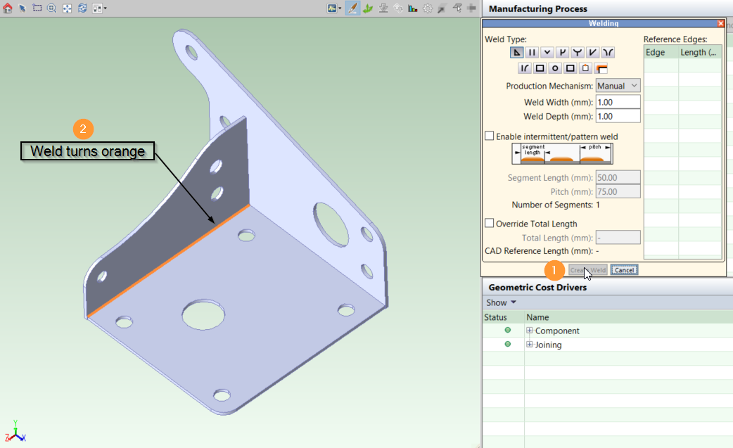
Click Create Weld button. The weld turns orange in the Viewer Panel indicating it has been applied to the assembly:
-
After you have created any more welds, close the weld tool pane by clicking Cancel or the red X in the top right corner of the window.
-
The welds now appear in the Geometric Cost Drivers panel.
Check that all the information for the welds is correct here. You can double click on the weld name to edit any incorrect weld properties.
-
You can now re-cost the assembly as normal, including your welds.
Note: Ensure all sub-components in the assembly have been costed - see Analyze Subassemblies Using the Initialize Option.
Create Spot Welds
For Spot Welds, select Spot as the Weld Type and select an edge or hole to be welded.
Adjacent surfaces cannot be selected, and you cannot manually point and click to define individual spot locations. Instead, the spot welds are applied along the selected edge across the entire GCD.
To indicate multiple spot weld segments, check Enable Intermittent/Pattern Weld and set the Pitch (the distance between welds). Since each spot is treated as size zero, the pitch defines their spacing. The Number of Segments is calculated as: rounddown(Total Length ÷ Pitch) + 1.
For example, an edge of 245 mm with a pitch of 25 mm results in 10 segments: rounddown(245 ÷ 25) + 1 = 9 + 1 = 10 segments.
Edit Virtual Welds
-
Open an assembly.
-
Highlight a virtual weld either in the Component Viewer or in the GCDs pane.
-
Right-click the Virtual Weld and select Edit from the menu. The weld properties window is displayed.
-
You can select multiple welds by holding down the Ctrl key or the Shift key and clicking the welds.
-
-
Edit the weld properties as required.
-
Click OK.
Copy Virtual Welds
You can import welds from other assemblies.
Caution: The source assemblies must have geometry that is very similar to the open assembly; they must be different versions of the same assembly that differ only in a few details or which have different part numbers
-
Open an assembly.
-
Click Scenario > Copy Welds From... .
-
Use the Search window to find and open the assembly with the welds that you want to copy.
-
All existing virtual welds in the destination assembly are discarded and are replaced by the imported welds.
-
The imported welds retain the same weld IDs they had in the source assembly.
-
Any non-virtual (CAD-defined) welds in the target assembly are kept, but they moved to the end of the weld list (they have IDs that start after the imported weld ids).
-
After copying, aP Pro generates a Copy Welds Analysis report to help you evaluate the success of the copy operation - see Assembly Reports.
Tip: You can also run this report at any time using the Reports > Spreadsheet Reports option.
Copy Limitations
As the two assemblies that the welds are being copied between must be substantially similar, the following limitations apply:
-
Mirrored assemblies are not supported. Some welds may get copied, but the results reliable.
-
Any weld that has more than about a 30% change in location or size shows varied copy results.
Delete Virtual Welds
-
Open an assembly.
-
Highlight a virtual weld either in the Component Viewer or in the GCDs pane. To select several welds, hold the Ctrl button while you click on welds.
-
Right-click the Virtual Weld and select Delete (in the Component Viewer) or Remove (in the GCDs pane) from the menu.